ATmega32 Timer1 Fast PWM Beispielcode
Der Timer1 des ATmega32 erzeugt in diesem Programm ein Fast PWM Signal.
|
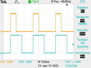
Beschreibung Der Timer 1 arbeitet in diesem Programm im Fast PWM Mode. Die beiden Ausgänge OC1A und OC1B werden auf null gesetzt, wenn der Timer von 255 auf 0 zurückspringt. OC1A wird auf eins gesetzt, wenn der Timer 63 erreicht (25% PWM). Der Ausgang OC1B hat mit dem Comparewert von 127 einen Tastgrad von 50%. |
Please visit: the four
|

C Sourcecode
#include <avr/io.h>
int main(void)
{
DDRD = 0x30; // Set Port D4 and d5 as Output
TCCR1A = (1<<WGM10)|(1<<COM1A1) // Set up the two Control registers of Timer1.
|(1<<COM1B1); // Wave Form Generation is Fast PWM 8 Bit,
TCCR1B = (1<<WGM12)|(1<<CS12) // OC1A and OC1B are cleared on compare match
|(1<<CS10); // and set at BOTTOM. Clock Prescaler is 1024.
OCR1A = 63; // Dutycycle of OC1A = 25%
OCR1B = 127; // Dutycycle of OC1B = 50%
for(;;); // Endless loop;
// main() will never be left
return 0; // This line will never be executed
}
Download lauffähiges C-File mit ASCII-Schema: Downloadlink
Signalplots
|
|
Gelb: PWM Signal an PD5 (OC1A)
|