ATmega16 Timer0 Normal Mode
Sourcecode Beispiel um auf dem ATmega16 den Timer0 im Normal Mode mit Overflow Interrupt zu betreiben.
|
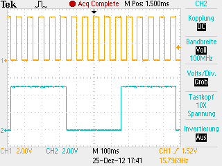
Beschreibung Timer 0 wird im Normal Mode betrieben um zwei Rechtecksignale an PA0 und PA1 zu erzeugen. Der Prescalerr ist auf 1024 eingestellt. Der Timer zählt von 0 bis 255. Dann tritt ein Overflow ein und er beginnt von vorne. Der Overflow löst den Overflow Interrupt aus. In der Interruptroutine wird PA0 jedes mal und PA1 jedes zehnte Mal getoggelt. Die Zehn durchläufe werden mit einem Zähler und einem Switch Block innerhalb der Interruptroutine abgezählt. |
Please visit: the four
|

C Sourcecode
#include <avr/io.h>
#include <avr/interrupt.h>
volatile unsigned int overflowCounter = 0; // Counts the overflows
int main(void)
{
DDRA = 0x03; // Setup PA0 and PA1 as output
TIMSK |= (1<<TOIE0); // Enable Timer 0 Overflow interrupt
TCCR0 |= (1<<CS00)|(1<<CS02); // Start timer0 with prescaler 1024
sei(); // Set the I-bit in SREG
for(;;); // Endless loop
// main() will never be left
return 0; // This line will never be executed
}
// Interrupt subroutine for timer 0 overflow
ISR(TIMER0_OVF_vect)
{
overflowCounter++; // Increment overflowcounter
PORTA ^= 0x01; // Toggle PA0
switch (overflowCounter) // Switch overflowcounter
{
case 10: // Is the overflowcounter = 10?
PORTA ^= 0x02; // Toggle PA1
overflowCounter = 0; // Reset overflowcounter
break; // Leave the switch block
default: // If the overflowcounter is not 10
break; // Just leave the switch block
}
} // End of the timer 0 overflow
// interrupt subroutine
Download C-Sourcefile mit ASCII-Schema: C-Sourcefile mit ACII-Schema
Signalplot
|
|
Gelb: Rechteck Signal an PA0 |